Brushless Motors BLV Series
BLV620KM50F-2
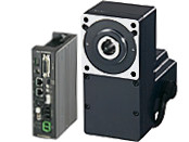
Gearhead / Motor / Control Circuit
| การจำแนกประเภทผลิตภัณฑ์ | ชื่อผลิตภัณฑ์ | รายการราคา | วันที่จัดส่ง |
|---|---|---|---|
| Gearhead / Motor / Control Circuit | BLV620KM50F-2 | THB 40,250 | สินค้าที่จะยกเลิกการผลิต (30.1.2026 order deadline) |
- *กรุณาติดต่อเราหากต้องการสั่งซื้อสินค้านี้
- *สินค้านี้จะหยุดผลิตในวันที่ 31.3.2026
รวม
- Motor: None
Gearhead: Mounting Screws, Parallel Key, Safety Cover (with Screws)
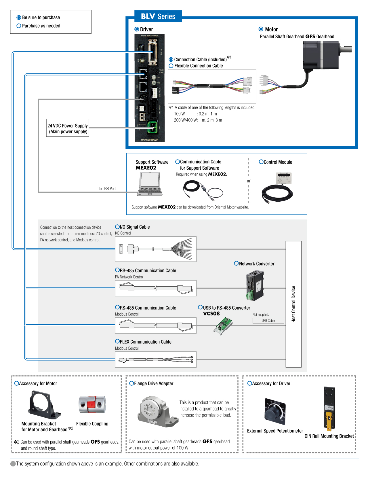
Control Circuit: Power Supply Connector
Connection Cable (2 m)
ข้อมูลเฉพาะ
ดาวน์โหลดข้อมูล
ข้อมูลเฉพาะอื่น ๆ
Common Specifications
- Standard Model: These specifications apply when the basic motor and driver package is used.
- Expanded Model: These specifications apply when a data setter (OPX-2A) (sold separately), support software (MEXE02), or communication is used.
| Item | Standard Model | Expanded Model *1 | |
|---|---|---|---|
| Speed Setting Methods |
Select one of the following methods.
|
Select one of the following methods.
|
|
| Acceleration Time and Deceleration Time | Acceleration and deceleration time potentiometer (VR2): 0.2~15 sec (at 3000 r/min with no load) |
Select one of the following methods.
or communication setting: 0.2~15 sec (Time to reach the set rotation speed) |
|
| Multi-Speed Setting Methods |
2-Speed:
1 speed by internal speed potentiometer and
1 speed with external analog setting |
Select one of the following methods.
6 speeds and 2 analog settings*2 *2 1 speed with internal speed potentiometer (VR1) and 1 speed with external analog setting |
|
| Torque Limiting Function | Setting Method | Torque limiting potentiometer (VR3) |
Select one of the following methods.
or communication settings |
| Setting Range | 0~200% (assuming the motor's rated torque is 100%) Factory setting: 200% |
0~200% (assuming the motor's rated torque is 100%) *3 Factory setting: 200%. *3 Digital setting (OPX-2A or MEXE02) or communication settings can be set in 1% increments |
|
| Input Signals | Photocoupler input method, input resistance 3.3 kΩ Operation via internal power supply: 15 VDC±10% Connectable external DC power supply: 24 VDC -15∼+20% current 100 mA min. Sink logic/source logic: switchable (factory-set sink logic) |
||
| FWD, REV, STOP-MODE, M0, ALARM-RESET, MB-FREE |
Any signal can be assigned to general-purpose input X0∼X5 (6 points) FWD (START/STOP), REV (RUN/BRAKE), STOP-MODE (FWD/REV), MB-FREE, EXT-ERROR, ALARM-RESET, H-FREE, HMI, M0, M1, M2 Terms in parentheses are for 3-wire mode |
||
| Output Signals | Open-Collector Output External operating conditions Control voltage 100 W, 200 W: 30 VDC or less, 400 W: 53 VDC or less General-purpose output Y0, Y1: 100 mA or less, SPEED-OUT: 10 mA or less |
||
| SPEED-OUT, ALARM-OUT1 (Y0), WNG (Y1) |
SPEED-OUT Arbitrary signal assignment to general purpose output Y0, Y1 (2 points) is possible. ALARM-OUT1, WNG, MOVE, TLC, VA, DIR, ALARM-OUT2 |
||
| Protective Function |
Overload, sensor error, sensor error at power-on, Overvoltage, undervoltage, overspeed, overcurrent, EEPROM abnormal, main circuit overheat, external stop, prevention of operation at power-on, communication switch setting error Main circuit output error |
||
| Warning | Main circuit overheat, undervoltage, overload, operation prohibition | ||
| Maximum Extension Distance | 100 W: 1.5 m between motor and driver (including motor cable 0.5 m) 200 W, 400 W: 3.5 m between motor and driver (including motor cable 0.5 m) |
||
| Time Rating | Continuous | ||
- *1
- What can be set in the driver volume (VR1, VR2, VR3) or external analog settings can be changed in the parameters.
- The torque limiting value may cause an error of up to ±20% (at rated torque and rated speed) between the setting value and the generated torque, depending on the setting speed, power supply voltage, and motor cable extension distance.
General Specifications
| Item | Motor | Driver | |
|---|---|---|---|
| Insulation Resistance | 100 MΩ or more when a 500 VDC megger is applied between the windings and the case after continuous operation under normal ambient temperature and humidity. |
After continuous operation at normal ambient temperature and humidity, the value measured with a 500 VDC megger between the power supply input and the heat sink is min. 100 MΩ. |
|
| Dielectric Strength | No abnormality is observed even with an application of 0.5 kVAC at 50 Hz between the coils and the case for 1 minute after continuous operation at normal ambient temperature and humidity. |
After continuous operation at normal ambient temperature and humidity, the value measured with a 0.5 kVDC megger between the power supply input and the heat sink is min. 100 MΩ. |
|
| Temperature Rise | After continuous operation at normal temperature and humidity, the measured value using the thermocouple method is 60 °Cmax. for the temperature rise of the coils and 50 °C max. for the temperature rise on the case surface.*1. |
After continuous operation at normal ambient temperature and humidity, the measurement value of the temperature rise of the heat sink is 50 °C max. using the thermocouple method. |
|
| Operating Environment | Ambient Temperature | 0~+40°C | |
| Ambient Humidity | 85 % max. (Non-condensing) | ||
| Altitude | Up to 1000 m above sea level | ||
| Atmosphere | Cannot be used in special environments such as corrosive gas, no dust, radioactive materials, magnetic fields, or vacuums | ||
| Vibration | Not subject to continuous vibration or excessive shock In conformance with JIS C 60068-2-6, "Sine-wave vibration test method" Frequency Range: 10~55 Hz, Half Amplitude: 0.15 mm, Sweep Direction: 3 directions (X, Y, Z), Number of Sweeps: 20 times |
||
| Storage Conditions*2 | Ambient Temperature | Electromagnetic Brake Motor 100 W Type: -20~+70°C (Non-freezing) Other: -25~+70°C (Non-freezing) |
-25~+70°C (Non-freezing) |
| Ambient Humidity | 85 % max. (Non-condensing) | ||
| Altitude | Up to 3000 m above sea level | ||
| Atmosphere | No corrosive gas, no dust, no water, no oil. Cannot be used in a radioactive area, magnetic field, vacuum, or other special environments. | ||
| Thermal Class | 120 (E) | − | |
| Degree of Protection | 100 W Type: IP65 (excluding Connector part) 200 W, 400 W Type: IP40 |
IP20 | |
- *1
- Attach round shaft types to a heat sink (Material: aluminum) of one of the following sizes to maintain a motor case surface temperature of 90 °C max.
200 W Type: 200x200 mm, 5 mm thickness
400 W Type: 250x250 mm, 6 mm thickness - *2
- The value for storage condition applies to short periods such as the period during transport.
Note
- Do not measure insulation resistance or perform a dielectric strength test the motor and driver are connected.
Communication Specifications
Modbus Communication Specifications
| Item | Specifications |
|---|---|
| Communication Protocol | Modbus Protocol (Modbus RTU mode) |
| Electrical Characteristics | EIA-485 Compliant The maximum total extension length of the communication cable is 50 m when using shielded twisted-pair wires (TIA/EIA-568B CAT5e or better recommended). |
| Transmission/Reception Mode | Half Duplex |
| Transmission Rate | 9600bps, 19200bps, 38400bps, 57600bps, 115200bps |
| Physical Layer | Asynchronous Mode (Data: 8 bits, Stop Bit: 1 bit or 2 bits, Parity: none, even, or odd) |
| Maximum Number of Connected Axes | 31 axes |
Communication Specifications for Network Converter Connection
| Item | Specifications |
|---|---|
| Communication Protocol | Oriental Motor’s Original Communication Protocol |
| Electrical Characteristics | EIA-485 Compliant The maximum total extension length of the communication cable is 50 m when using shielded twisted-pair wires (TIA/EIA-568B CAT5e or better recommended). |
| Transmission/Reception Mode | Half Duplex |
| Transmission Rate | 625000bps |
| Physical Layer | Asynchronous mode (Data: 8 bits, Stop Bit: 1 bit, Parity: none) |
| Maximum Number of Connected Axes | Depends on the number of network converters that can be connected NETC01-CC: 6 or 12 axes (depends on the operation mode) NETC01-M2, NETC01-M3: 8 or 16 axes (depends on the operation mode) NETC01-ECT: 16 axes |
Permissible Radial Load and Permissible Axial Load
Combination type with a parallel shaft gearhead
| Product Name | Gear Ratio | Permissible Radial Load | Permissible Axial Load Load N |
||
|---|---|---|---|---|---|
| 10 mm From the End of the Output Shaft N |
20 mm From the End of the Output Shaft N |
||||
| BLV510 | 5 | 300 | 400 | 150 | |
| 10, 15, 20 | 400 | 500 | |||
| 30, 50, 100, 200 | 500 | 650 | |||
| BLV620 BLV640 |
5, 10, 15, 20 | At 100~3000 r/min | 550 | 800 | 200 |
| At 4000 r/min | 500 | 700 | |||
| 30, 50 | At 100~3000 r/min | 1000 | 1250 | 300 | |
| At 4000 r/min | 900 | 1100 | |||
| 100, 200 | At 100~3000 r/min | 1400 | 1700 | 400 | |
| At 4000 r/min | 1200 | 1400 | |||
Combination type with a hollow shaft flat gearhead
| Product Name | Gear Ratio | Permissible Radial Load | Permissible Axial Load N |
||
|---|---|---|---|---|---|
| 10 mm From Mounting Surface N |
20 mm From Mounting Surface N |
||||
| BLV510 | 5, 10 | 900 | 770 | 500 | |
| 15, 20 | 1300 | 1110 | |||
| 30, 50, 100, 200 | 1500 | 1280 | |||
| BLV620 BLV640 |
5*, 10 | At 100~3000 r/min | 1230 | 1070 | 800 |
| At 4000 r/min | 1130 | 990 | |||
| 15, 20 | At 100~3000 r/min | 1680 | 1470 | ||
| At 4000 r/min | 1550 | 1360 | |||
| 30, 50, 100 | At 100~3000 r/min | 2040 | 1780 | ||
| At 4000 r/min | 1900 | 1660 | |||
- * BLV640only
Round Shaft Type
| Product Name | Permissible Radial Load | Permissible Axial Load N |
|
|---|---|---|---|
| 10 mm From the End of the Output Shaft N |
20 mm From the End of the Output Shaft N |
||
| BLV620 BLV640 |
197 | 221 | 25 |
Permissible Radial Load Calculation
The formula for calculating the permissible radial load varies depending on the mechanism.
When One Side of the Load Shaft is Not Supported by the Bearing Unit
The radial load is the most difficult mechanism. A Stepped Type Load Shaft is recommended.
| Product Name | Permissible Radial load W [N] |
|---|---|
| GFS2G□FR |
\(\begin{align} \mathrm{W} [\mathrm{N}] = \frac{36}{36 + \mathrm{Lp}} \times \mathrm{F}_0 [\mathrm{N}] \end{align}\)
|
| GFS4G□FR |
\(\begin{align} \mathrm{W} [\mathrm{N}] = \frac{40}{40 + \mathrm{Lp}} \times \mathrm{F}_0 [\mathrm{N}] \end{align}\)
|
| GFS5G□FR |
\(\begin{align} \mathrm{W} [\mathrm{N}] = \frac{50}{50 + \mathrm{Lp}} \times \mathrm{F}_0 [\mathrm{N}] \end{align}\)
|
| GFS6G□FR |
\(\begin{align} \mathrm{W} [\mathrm{N}] = \frac{60}{60 + \mathrm{Lp}} \times \mathrm{F}_0 [\mathrm{N}] \end{align}\)
|
When One Side of the Load Shaft is Supported by the Bearing Unit
| Product Name | Permissible Radial load W [N] |
|---|---|
| GFS2G□FR GFS4G□FR GFS5G□FR GFS6G□FR |
\(\begin{align} \mathrm{W} [\mathrm{N}] = \frac{\mathrm{B}}{\mathrm{B} - \mathrm{Lp}} \times \mathrm{F}_0 [\mathrm{N}] \end{align}\)
|
| Product Name | Rotation Speed | Gear Ratio | F0 [N] |
|---|---|---|---|
| GFS2G□FR | At 3~3000 r/min | 5, 10 | 570 |
| 15~200 | 630 | ||
| At 4000 r/min | 5, 10 | 520 | |
| 15~200 | 580 | ||
| GFS4G□FR | At 3~3000 r/min | 5, 10 | 1000 |
| 15~200 | 1500 | ||
| At 4000 r/min | 5, 10 | 910 | |
| 15~200 | 1370 | ||
| GFS5G□FR | At 3~3000 r/min | 5, 10 | 1080 |
| 15, 20 | 1550 | ||
| 30~200 | 1800 | ||
| At 4000 r/min | 5, 10 | 980 | |
| 15, 20 | 1430 | ||
| 30~200 | 1680 | ||
| GFS6G□FR | At 3~3000 r/min | 5, 10 | 1430 |
| 15, 20 | 1960 | ||
| 30~100 | 2380 | ||
| At 4000 r/min | 5, 10 | 1320 | |
| 15, 20 | 1810 | ||
| 30~100 | 2210 |
มาตรฐาน
Regulations and Standards Materials
Documents about compliance with regulations and standards can be downloaded from the "Data Download" tab on the product details page.
(The types of files available for download vary by product.)
Explanations of the Global Laws, Regulations and Standards can be found here.
Information about our compliance with safety standards for each of our product models can be found here.
Hazardous Substances
The product does not contain any substances (10 substances) exceeding the regulation values of the RoHS Directive (2011/65/EU, 2015/863/EU).
การกำหนดค่าระบบ
สินค้าที่เกี่ยวข้อง
Network Converter
| Products | Features | ||
|---|---|---|---|
| Products |
NETC01-CC
|
Features |
[CC-Link Ver.1.1 Compatible] By connecting a network converter, you can complete the wiring process with a single dedicated cable approved for the CC-Link communication protocol. |
| Products |
NETC01-M2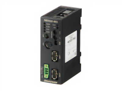
|
Features |
[MECHATROLINK-II Compatible] By connecting a network converter, the wiring process can be completed with a single dedicated cable approved for the MECHATROLINK-II communication protocol. |
| Products |
NETC01-M3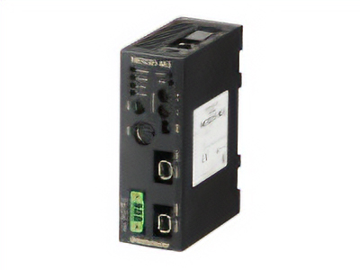
|
Features |
[MECHATROLINK-III Compatible] By connecting a network converter, the wiring process can be completed with a single dedicated cable approved for the MECHATROLINK-III communication protocol. |
| Products |
NETC01-ECT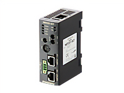
|
Features |
[EtherCAT Compatible] By connecting a network converter, Oriental Motor's FLEX compatible products can be controlled in an EtherCAT communication environment. |