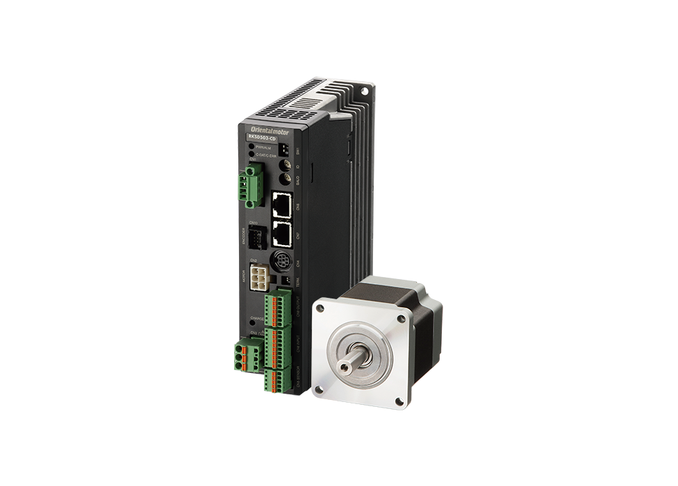
Stepper Motors
RKII Series

- AC input
- High torque, low vibration
คุณลักษณะ | Stepper Motor RKII Series
Reduced Total Cost of Equipment
Equipment Can be Miniaturized
Optimized arrangement of internal parts has made the drivers compact and slim. Multiple drivers can now be installed in contact with each other, making it possible to increase the number of axes within the same equipment space.
- When drivers are installed in contact with each other, the allowable ambient temperature range is 0~40 °C.

Reduces Power Consumption by a Maximum of 47 %
By optimizing the motor material, loss has been greatly reduced, and power consumption has been reduced by up to 47 %.
This results in reduced electricity costs as well as reduced CO2 emissions.
- *Refer to here for details on high efficiency motors.
Power Consumption Comparison

Operating Conditions
-
- Rotation Speed
- 1000 r/min
-
- Load Torque
- 0.47 N·m
-
- operating Time
- 24-hour operation
(70 % operation, 25 % standby, 5 % stop), 365 days/year
Comparison of Power Consumption, etc.

Reduction in Effects of Heat within Equipment
Heat generation has also been reduced due to reduced motor loss. This reduces the effects upon other devices of heat within the sealed equipment, and reduces labor and cost spent on measures using fans and heat sinks to counteract heat generation.
Motor Surface Temperature Comparison When Operating Under the Same Conditions

Temperature Distribution by Thermography

Performance and Functions That Enhance Equipment Reliability
Highly Accurate Positioning
The positioning accuracy of the RKII Series is ±0.05˚ (±3 min). When used in combination with a ball screw as shown in the figure below, the positioning accuracy is ±1.4 μm. The accuracy of a regular ground ball screw is ±10 μm, and thus the accuracy is high enough for positioning operation.

Demonstration of stopping accuracy for RKII Series using microscope vs using objective micro gauge
Small Size and High Torque
The RKII Series is compact and produces high torque. The torque of the 42 mm frame size has increased 50 %. This contributes to reduced positioning time and increased equipment takt time. The series includes 60 mm and 85 mm frame size to cover a wide torque range.
-
- Note
- For 60 mm and 85 mm frame size products, the torque is equivalent to the conventional product.
Torque Comparison With Conventional Products (□42 mm)

Reference Output Power for Stepper Motor
The output power (W) of a servo motor is indicated as "rated output power" when it is running at "rated speed."
On the other hand, as stepper motors, with their characteristic high precision positioning and high torque at medium and low speeds, have no "rated speed," no "rated output power" is given.
The link below offers a list for your reference for how RKII Series standard type motors’ torque values correspond to what W of servo motors’ rated torque.
Reduced Positioning Time
Conventional stepper motors are sometimes used in applications where heat generation needs to be reduced by lowering the operating current and lowering the torque. The RKII Series uses a high efficiency motor with low heat generation, so the positioning time can be reduced by maximizing the motor's torque.
Comparison of Torque via Different Operating Currents

Comparison of Takt Time via Different Operating Currents

Operating Conditions
-
- Load Inertia
- 4 × 10⁻⁴ [kg·m2]
-
- Load Torque
- 0.2 [N·m]
-
- Travel Amount
- 180°
-
- Safety Factor
- 2
Significantly Reduced Vibration and Noise
Utilizing a full-time microstepping driver with full digital control improves the vibration characteristics of the 5-phase stepper motor. Currents are controlled digitally and calculated by a high-performance CPU.
The change from the conventional total current detection PAM control to individual phase current detection PWM control has changed the current flowing in each phase into sine wave currents. As a result, vibration and noise are significantly reduced.
Motor Current Waveform (Theoretical data)

Vibration Characteristics Comparison

Step Angle is Easy to Set
Pulse Input Type
32 different step angles can be set. Selection can be made to suit the mechanism, and step angle is also built into the 2-phase stepper motor. Simply select the setting with the switch; no dedicated software or control module is required.

Built-In Controller Type
This can be set within the range of 200 p/r~200000 p/r.
Setting can be done by a control module, data setting software or RS-485 communication.

Various Protective Functions Equipped
Protective functions are equipped to quickly respond when trouble occurs. The problem can be quickly identified using the blink count of the alarm LED.
[Examples of Alarm Types]
- Main circuit overheating
- overvoltage
- Command pulse error
- Overcurrent
- Undervoltage
- Electrolytic capacitor error
- EEPROM error
- CPU error
- Automatic electromagnetic brake control error

Simple Wiring and Selection
Simple Wiring and Selection
Easy Wiring
Screwless I/O connectors eliminate the need for soldering or dedicated crimping tools. The motor connector can be connected easily by using a dedicated cable. This will reduce wiring time, prevent mis-wiring and reduce maintenance.

This video shows "wiring," "data setting," and "operation confirmation
Simple Selection
Using the Motor Sizing Service
Motor sizing such as torque computation is performed on the customer's behalf by specialist staff member.
Not only will we recommend the product best suited to your mechanism, but also introduce accessories and show you the calculation process.
This is a free service that provides a response in as little as 2 hours.
Click here for motor sizing service
Using the Motor Sizing Tool
This tool lets you select a product by simply entering the values of the mechanism and operating conditions online.

2 types of drivers to choose from
RKII Series drivers are available in two types, "Built-in controller type" and "Pulse input type," to match the host controller used by the customer.

Control System Configuration for Built-In Controller Type
I/O Control
Switch Box Usage Example

Operation data is set in the driver, and the motor can be started or stopped simply by connecting to the switch at hand. Control can be performed easily without using PLC.
PLC Usage Example

When using PLC, an operation system can be configured by connecting directly to an I/O module. A positioning module is not necessary on the PLC side, saving space and simplifying the system.
PLC and Touch Screen Usage Example

Normally, the motor is started and stopped with I/O. Changing the operation data settings and displaying the monitors and alarms are performed with the touch screen using Modbus (RTU) communication. When there is a lot of setup work, changes can be easily performed on the touch screen, and the burden of creating ladders is reduced.
Control via Modbus (RTU)/RS-485 Communication
RS-485 communication can be used to set operation data and parameters, as well as input operation commands. Up to 31 drivers can be connected to 1 serial communication module. It also comes with a function that enables multiple axes to be started simultaneously. The protocol is supported by Modbus (RTU) and can be used to connect to touch screens and computers.
Control via Industrial Network
By using a network converter (sold separately), CC-Link, MECHATROLINK or EtherCAT communication is possible. All of these can be used to set operation data and parameters, as well as input operation commands.
Built-In Controller Type
Because the driver has the information necessary for motor operation, the burden on the host PLC is reduced. The system configuration when using multi-axis control has been simplified.
Settings are configured using a control module (sold separately), support software, or RS-485 communication.

Operation Types
In the built-in controller type, the operating speed and travel amount of the motor are set with operation data, and operation is performed according to the selected operation data. There are 4 types of motor operations.
Main Functions
Group Send Function
This function enables multiple axes to be started simultaneously using Modbus (RTU) communication or industrial network. Multiple drivers can be grouped together, and when an operation command is sent to the master driver, all the drivers that belong to the same group as the master driver will operate simultaneously.
- Modbus (RTU) Control
- Simultaneous starting, changing travel amount/speed, and monitoring are supported.
- Industrial network control
- Simultaneous start only
Example of Modbus (RTU) Communication Control

Teaching Function
Teaching can be done using the control module OPX-2A (sold separately) or the MEXE02 support software. Move the table to the target position, and store the position data for that time as the positioning data.

Click here for information about the support software
Connection With Third-Party Devices
Information about connecting Oriental Motor network converters to other companies' "touch screen" and "PLC network modules" is available here.
You can download screen samples and connection guides for the applicable manufacturer, and find information on communication cables that allow direct connection between Oriental Motor’s products and other manufacturers' devices. We hope you will find this information useful in reducing the time required for program design and start-up.
When connecting to a "touch screen"
[Examples of Applicable Manufacturers]
Schneider Electric Japan Holdings Ltd.

When connecting to a "PLC network module"
[Examples of Applicable Manufacturers]
OMRON Corporation / Hitachi Industrial Equipment Systems Co., Ltd. / Mitsubishi Electric Corporation / YASKAWA Electric Corporation
Product Line
| Driver Type | Motor Type | Frame Size [mm] |
Maximum Holding Torque [N·m] |
Backlash [arcmin] |
Basic Step Angle [゜] |
Electromagnetic Brake | ||
|---|---|---|---|---|---|---|---|---|
| Equipped | Not Equipped | |||||||
| Built-In Controller Type / Pulse input type |
Standard | 42 | 0.14~0.27 | - | 0.72 | ○ | ○ | |
| 60 | 0.52~1.77 | ○ | ○ | |||||
| 85 | 2.1~6.3 | ○ | ○ | |||||
| Standard With Encoder*1 |
42 | 0.14~0.27 | - | 0.72 | - | ○ | ||
| 60 | 0.52~1.77 | - | ○ | |||||
| 85 | 2.1~6.3 | - | ○ | |||||
| Backlashless |
TS geared (Spur gear mechanism) |
42 | 0.5~2.3 | 15~45 | 0.024~0.2 | ○ | ○ | |
| 60 | 1.8~6 | 10~35 | ○ | ○ | ||||
| 90 | 6~25 | 10~25 | ○ | ○ | ||||
| FC Geared*2 (Face gear mechanism) |
42 | 0.7~3 | 15~25 | 0.024~0.1 | - | ○ | ||
| 60 | 2.5~10.5 | 10~15 | - | ○ | ||||
| PS Geared (Planetary gear mechanism) |
42 | 1~3 | 15 | 0.0144~0.144 | ○ | ○ | ||
| 60 | 3.5~8 | 7~9 | ○ | ○ | ||||
| 90 | 14~37 | ○ | ○ | |||||
| Non-backlash |
Harmonic geared (Harmonic drive®) |
42 | 3.5~5 | 0 | 0.0072~0.0144 | ○ | ○ | |
| 60 | 7~10 | ○ | ○ | |||||
| 90 | 33~52 | ○ | ○ | |||||
- *1
- Built-in controller type only
- *2
- Refer to here for details on FC geared type.
- Harmonic drive® is a registered trademark or a trademark of Harmonic Drive Systems Inc.
จำกัดผลิตภัณฑ์
ดาวน์โหลด
Operating Manual
Support Software
รายการและข้อมูลที่เกี่ยวข้อง

Combining with Other Manufacturers' Products


