Torque Motors TM Series
TM306A-9SU

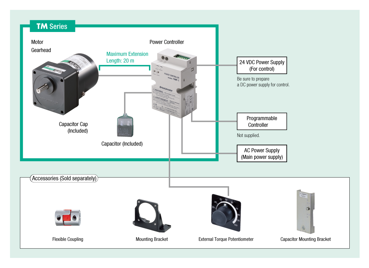
Gearhead / Motor / Control Circuit
| การจำแนกประเภทผลิตภัณฑ์ | ชื่อผลิตภัณฑ์ | รายการราคา | วันที่จัดส่ง |
|---|---|---|---|
| Gearhead / Motor / Control Circuit | TM306A-9SU | THB 8,713 | สินค้าที่จะยกเลิกการผลิต (30.1.2026 order deadline) |
- *กรุณาติดต่อเราหากต้องการสั่งซื้อสินค้านี้
- *สินค้านี้จะหยุดผลิตในวันที่ 31.3.2026
รวม
- Motor: Capacitor, Capacitor Cap
Gearhead: Mounting Screws, Parallel Key
Control Circuit: None
ข้อมูลเฉพาะ
ลักษณะเฉพาะ
ขนาด
ข้อมูลเฉพาะอื่น ๆ
Common Specifications of the Circuit Section
| Item | Specifications |
|---|---|
| Power Supply Input | Single phase 100/110/115 V ± 10 % 50/60 Hz Single phase 200/220/230 V ± 10 % 50/60 Hz |
| Control Power Supply | 24 VDC±10 %, 100 mA min. |
| Torque Setting Method |
|
| Input Signals | Photocoupler Input: Input resistance of 4.7 kΩ CW input, CCW input, INT/EXT switching input, alarm reset input |
| Output Signals | Open-collector output 4.5~26.4 VDC max. 40 mA max. Alarm Output |
| Protective Function | Under the following circumstances, the motor will stop, the alarm LED will blink, and an alarm signal will be output.
|
| Maximum Extension Distance | Between motor and power controller 20 m |
General Specifications
| Item | Motor Part | Power Controller Part | |
|---|---|---|---|
| Insulation Resistance | After rated operation at normal ambient temperature and humidity, the measurement between the coils and the case is 100 MΩ min. using a 500 VDC megger. | After continuous operation at normal ambient temperature and humidity, the measurement value between the main circuit terminal and the control circuit terminal or the main circuit terminal and the case is 100 MΩ min. using a 500 VDC megger. | |
| Dielectric Strength | No abnormality is observed even with an application of 1.5 kVAC at 50 Hz between the coils and the case for 1 minute after rated operation at normal ambient temperature and humidity. | No abnormality is observed even with an application of 3.0 kVAC at 50 Hz or 60 Hz between the main circuit terminal and the control circuit terminal or the main circuit terminal and the case for 1 minute after continuous operation at normal ambient temperature and humidity. | |
| Temperature Rise | After a gearhead or equivalent heat sink * is connected for rated operation at normal ambient temperature and humidity, the measurement value of the winding temperature rise is 80 °C max. (when single-phase 100 VAC or single-phase 200 VAC) using the resistance change method. The value is 90 °C max. for others. | - | |
| Overheat Protective Device | Built-in Thermal Protector (Automatic Return Type) Open: 130±5 ℃, Reset: 85±20 ℃ |
- | |
| Operating Environment | Ambient Temperature | Single-Phase 100 V, Single-Phase 200 V: -10~+50 °C (Non-freezing) Other Voltages: -10 to +40 °C (Non-freezing) |
0~+50 °C (Non-freezing) |
| Ambient Humidity | 85 % max. (Non-condensing) | ||
| Thermal Class | 130 (B) | - | |
| Degree of Protection | IP20 | IP20 | |
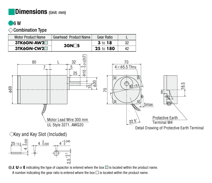
- *Heat sink size (Material: Aluminum)
| Motor Type (Output) | Size (mm) | Thickness (mm) |
|---|---|---|
| TM203 Type (3 W) | 115 x 115 | 5 |
| TM306 Type (6 W) | 125 x 125 | |
| TM410 Type (10 W) | 135 x 135 | |
| TM520 Type (20 W) | 165 x 165 |
Note
-
Do not do insulation resistance measurement or perform pressure tests with a connection between the motor and power controller.
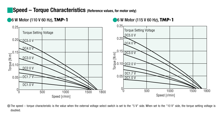
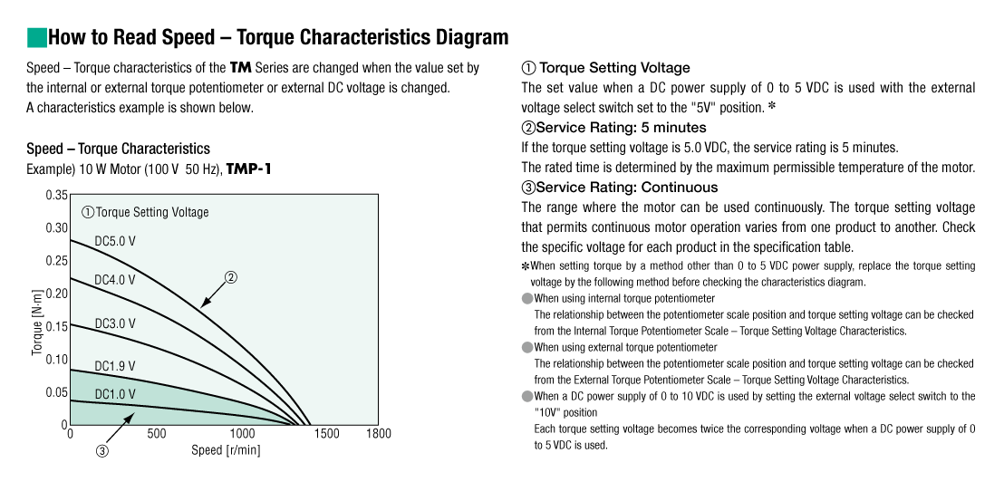
Output Torque
Torque motors have sloping characteristics, so they can be used at any rotation speed, from stop to maximum rotation speed. For the output shaft torque of the combination type, get confirmation of the rotation speed and torque to be used from the graph of rotation speed - torque characteristics and calculate using the following formula.
Output shaft speed of combination type NG
= motor speed × 1 / gearhead gear ratio
Output shaft torque of combination type TG
= motor torque × gearhead gear ratio × gearhead transmission efficiency
Note that the output shaft torque of the combination type does not exceed the starting torque.
| Gearhead Gear Ratio | Gearhead Transmission Efficiency |
|---|---|
| 3, 3.6, 5, 6, 7.5, 9, 12.5, 15, 18 | 81 % |
| 25, 30, 36 | 73 % |
| 50, 60, 75, 90, 100, 120, 150, 180 | 66 % |
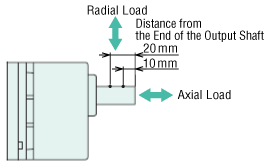
Permissible Radial Load and Permissible Axial Load of Gearhead
| Product Name | Gear Ratio | Maximum Permissible Torque N·m |
Permissible Radial Load N | Permissible Axial Load N |
|
|---|---|---|---|---|---|
| From Shaft End 10 mm |
From Shaft End 20 mm |
||||
| 2GN□S | 3~18 | 3.0 | 50 | 80 | 30 |
| 25~180 | 120 | 180 | |||
| 3GN□S | 3~18 | 5.0 | 80 | 120 | 40 |
| 25~180 | 150 | 250 | |||
| 4GN□S | 3~18 | 8.0 | 100 | 150 | 50 |
| 25~180 | 200 | 300 | |||
| 5GN□S | 3~18 | 10 | 250 | 350 | 100 |
| 25~180 | 300 | 450 | |||
มาตรฐาน
Regulations and Standards Materials
Documents about compliance with regulations and standards can be downloaded from the "Data Download" tab on the product details page.
(The types of files available for download vary by product.)
Explanations of the Global Laws, Regulations and Standards can be found here.
Information about our compliance with safety standards for each of our product models can be found here.
Hazardous Substances
The product does not contain any substances (10 substances) exceeding the regulation values of the RoHS Directive (2011/65/EU, 2015/863/EU).
การกำหนดค่าระบบ
สายเคเบิลและอุปกรณ์เสริม